The Standard, Application, and Advantage of FMC Mezzanine Modules
The article gives a brief description of the FMC standard that defines mezzanine modules designed for operation with the FPGA-based boards. The examples are shown using FMC mezzanine and FPGA-based carrier boards implemented in in accordance with the CompactPCI Serial and OpenVPX standards.
Requirements and approaches to the implementation of the external I/O interface is one of the most challenging problems faced by the developers of embedded systems. Regardless of the interface nature: Ethernet with optical or "copper" physical data transmission channel: analog or gigabit serial interface, –system developers need an efficient set of tools for the creation of the required combination of interfaces within a computing system. One of the ways to solve this problem is the use of the two-component system consisting of the carrier-board with the processing unit and a mezzanine module designed for implementation of input/output of signals. This approach is properly standardized and includes several form-factors of mezzanine modules, such as PMC and XMC, and carriers in the designated implementation, where the devices in VME, VPX, CompactPCI, AdvancedTCA, MicroTCA, PCI, PXI form-factors are the most commonly used ones.
The interaction between the carrier-board and mezzanine PMC and XMC modules are based on the PCI and PCI Express buses, respectively.

Standard of FMC Modules
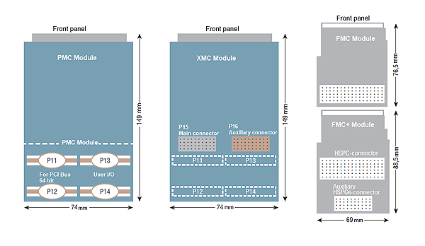
The widespread use of the FPGA (Field-Programmable Gate Array) technology is yet more proof that the approach dividing the components of the embedded computing system into input / output devices and mathematical processing units was correct and made it possible evolving to the standardization of I/O modules. In 2008, the development of the cross-platform standard ANSI / VITA 57.1 FPGA Mezzanine Card (FMC) was completed. This standard defined design and physical interface of the module with the carrier board (connector type, set of signals, their physical characteristics and location on the connector’s contacts). The protocol of interaction of the module with the carrier-board standard is not limited due to the wide variety of possible types of input/output interfaces. This is what makes the FMC module standard truly cross-platform and applicable to any carrier-boards (Figure 1), unlike PMC and XMC.
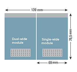
The FMC mezzanine modules have a form-factor with overall dimensions 69-76.5 mm - single width, or 139-76.5 mm - double width (Figure 2). The modules are connected as mezzanines with special carrier boards for data processing containing FPGA. The standard defines two connector options for FMC carrier and mezzanine modules, namely:
- 160-pin Low Pin Count (LPC) - 68 user signals (or 34 differential pairs of LVDS);
- 400-pin High Pin Count (HPC); - 160 user signals (or 80 differential pairs of LVDS). The LPC and HPC connectors are pin-compatible.

In addition to the LVDS differential pairs, the standard stipulates serial high-speed transceiver and clock lanes for them, providing the bandwidth capacity up to 1 Gb/s (in the future - up to 10 Gb/s) for each (in which case, there could be up to up to 10 of such lines in HPC, but only one line in LPC).
FMC+ Specification
In order to support a new class of data converters using the JESD204B serial interface instead of parallel LVDS, the FMC specification was improved to the FMC + specification.
This version, written in VITA 57.4, increases the number of serial transceiver lanes from 10 to 24, using a new high-speed version of the HPC connector with four more rows of contacts (HSPC connector). The new connector for FMC+ is designed for data transfer rates up to 28 Gb/s.
In addition to it, VITA 57.5 adds eight more Gigabit transceiver lanes to the FMC + module, increasing the length of the original FMC module by 12 mm to support the new 40-pin connector (HSPCe), as shown in the lower right corner in Figure 1. This increases the total number of full-duplex Gigabit serial (transceiver) lanes up to 32, which makes it possible to provide the maximum transfer rates of input/output data.
The FMC, unlike PMC and XMC, does not use standard industry interfaces, such as PCI or PCIe.
As an alternative, the FMC-module has a unique set of control and data transmission lines. Each of these lines is distinguished by signal level, quantity, bit depth and speed. At the clock frequency of 1 GHz, 80 differential data lines can provide 10 GB/s, although with the new FMC+ specification these values are doubled. The original FMC specification sets a target of 10 Gb/s for each of the ten transceiver lanes, providing a maximum overall data transfer rate of 10 GB/s. The new FMC+ specification with a bandwidth of 28 Gb/s with a maximum of 32 lines increases this maximum overall data transfer rate to 90 GB/s.
Advantages of FMC Technology
The mezzanine FMC modules have such input/output devices and primary signal processing units on them as ADC, DAC, DDC or interface transceivers. The exclusion of intermediate interface bridges enables you maximizing the data transfer bandwidth.
Further, the FMC technology makes it possible to significantly simplify the process of designing embedded systems and provides developers with a number of important advantages.
- Maximum bandwidth - individual data transfer rate up to 10 Gb/s with a total bandwidth of up to 100 GB/s and more between the mezzanine and the FPGA.
- Minimal latency time due to the exclusion of intermediate interface bridges, which also provides determinism of data delivery.
- Reduction of design complexity - I/O is connected to the FPGA directly, so the experience with standard protocols such as PCI, PCI Express or Serial RapidIO is not required. The possibility of direct connection between the mezzanine microchips and the FPGA of the carrier module, including via the multi-gigabit transceivers, is supported.
- Minimal system costs - Simplified system design reduces the costs for IP cores, development time and the costs for component parts for the finished product.
Application of FMC Mezzanine Modules
The FMC mezzanine modules have an extremely wide area of application that includes communication systems, radio detection and ranging systems, hydro acoustics systems, speech processing and recognition systems, laboratory equipment, industrial equipment automation systems, medical diagnostic systems, digital radio and television, etc. Perfectron (Table 1).
PERFECTRON Mezzanine FMC modules (Table1)
| External view | Name | Description |
|---|---|---|

|
2-channel Ethernet Mezzanine Module MIC1801 | Six-port Ethernet switch. Two ports of physical level interface Ethernet 1000Base-T / 100Base-TX / 10Base-T are routed to the front panel using RJ-45 connectors. Four ports (1 × GMII, 3 × SGMII) are routed to the FMC connector. In addition to these ports for data exchange, the mezzanine provides an opportunity of bidirectional input/output of up to 32 CMOS signals. |
 |
4-channel Mezzanine ADC Module of FMC standard with Conversion Rate of 10 bit and Maximum Sampling Frequency of up to 5 Gsamples/s MIC1811 | The module has a 4-channel ADC operating in three different configurations: - Single-channel mode with maximum sampling frequency of up to 5000 MHz; - Two-channel mode with maximum sampling frequency of 2500 MHz; - Four-channel mode with maximum sampling frequency of 1250 MHz. Both a signal from an external source and an internal signal from the carrier board can be used as the reference clock signal. Synchronization circuit with the external reference signal enables organizing a joint coherent signal processing by several modules. |
 |
16-channel Mezzanine ADC Module of FMC Standard with Conversion Rate of 14 bit and Maximum Sampling Frequency up to 125 Msample/s MIC1812 | The module has sixteen 14-bit ADC channels with a sampling frequency of up to 125 MHz. Both a signal from an external source and an internal signal from the carrier board can be used as the reference clock signal. Capability of clock signal output to the external connector ensures cascade connection of several boards for coherent analog-to-digital conversion. |
 |
2-channel Mezzanine DAC Module of FMC Standard with Conversion Rate of 14 bit and Maximum Sampling Frequency of 2,5 Gsamples/s MIC1821 | The module has two 14-bit DACs with a sampling frequency up to 2500 MHz. Both a signal from an external source and an internal signal from the carrier board can be used as the reference clock signal. Capability of clock signal output to the external connector ensures cascade connection of several boards for coherent digital-to-analog conversion. |
 |
1-channel Mezzanine DAC Module of FMC Standard with Conversion Frequency of 12 bit and Maximum Sampling Frequency of 3 Gsamples/s MIC1822 | The module contains a 12-bit digital-to-analog converter with a sampling frequency of up to 3000 MHz. Both a signal from an external source and an internal signal from the carrier board can be used as the reference clock signal. Capability of clock signal output to the external connector ensures cascade connection of several boards for coherent analog-to-digital conversion. |
 |
4-channel Transceiver Mezzanine Module of FMC Standard with Conversion Rate of 12 bit, Maximum Bandwidth of Signal Frequencies Spectrum up to 56 MHz and Carrier Frequency from 70 MHz up to 6 GHz MIC1831 | The module has two dual-channel transceiver chips with a maximum sampling frequency of input / output data up to 122.8 MHz. Bandwidth of the frequency spectrum of input / output signals is from 200 kHz to 56 MHz. Signal from the carrier board is used as the reference clock signal. The reference frequency for operation of the mixing unit in transceivers can be generated on the internal PLL (phase-locked loop) of transceivers from the reference clock signal coming from the carrier board or an external connector. |
 |
4/2-channel ADC/DAC Module of FMC Standard with JESD204B Interface MIC1832 | The module has two microchips of digital-to-analog converters with a maximum sampling frequency of 2800 MHz and two microchips of analog-to-digital converters with a maximum sampling frequency of 1250 MHz. This configuration enables implementing 4 independent channels of digital-to-analog conversion and 4 independent channels of analog-to-digital conversion. As a reference clock, a signal from the carrier-board is used. |
FPGA-based Carrier Modules of CompactPCI Serial and OpenVPX Standards (Table 2)
| External view | Name | Description |
|---|---|---|
 |
CompactPCI Serial FPGA-based Reconfigurable Computing Module of the Virtex-6 Family FPU500 |
The module is designed for building high-performance onboard systems for collecting and digital processing of real-time signals on the CompactPCI Serial 3U platform. Virtex-6 FPGA with 4 GB of DDR3 RAM is used as the FPU500 computing core. The integration of the FPU500 into the computing system is provided via the PCI-E x8 Gen2 bus. |
 |
CompactPCI Serial FPGA-based Reconfigurable Computing Module of Kintex UltraScale Family FPU502 |
The module is designed for building high-performance onboard systems for acquisition and digital processing of real-time signals on the CompactPCI Serial 3U platform. The module ensures full support of the SDAccel programming system, which makes it possible to use C ++ for the development of FPGA firmware. High performance of data processing, coming either through the PCI-Express Gen3 x8 interface or through the FMC module of the mezzanine, FPGA is provided by the Kintex UltraScale FPGA with two independent banks of RAM. Module synchronization system on the cross-board with Full Mesh Ethernet enables creating reference signals from any computing module. The reference signal can be entered into the system through the P4 slot from the Rear I/O of the module. |
 |
OpenVPX Artix-7 FPGA-based Reconfigurable Computing Module FPU1500 |
The module is designed for building high-performance onboard systems for acquisition and digital processing of signals, including in real-time, with the standard implementation OpenVXP 3U ANSI/VITA 46. As the computing kernel, FPU301 uses FPGA Artix-7 with 1 GB RAM DDR3. In order to enter the signals to the system you can install FMC mezzanine modules of various functional purpose compatible with the ANSI/VITA 57.1 specification. |
E.g. these mezzanine modules can be installed to the following FPGA-based carrier boards, implemented in accordance with the CompactPCI Serial and OpenVPX standards (Table 2) made by Perfectron.
